头部背景图片

Study on the Synthesis Process of Polyvinyl Acetate Emulsions

2025-09-12

Polyvinyl acetate emulsion (PVAc), commonly known as white latex, are widely used as a key polymer adhesive due to their ability to be directly modified with a variety of additives, excellent mechanical strength, and resistance to adhesive defects. Furthermore, their environmental friendliness as a water-based adhesive makes them particularly attractive. However, due to different synthesis processes, white latexes also have some drawbacks, such as limited water and heat resistance, generally high viscosity, and high solids content, which increase their cost.


1. Effect of Polyvinyl Alcohol on Emulsion Viscosity

Experiments were conducted using fully alcoholyzed PVA1799 and partially alcoholyzed PVA1788. The viscosity of the emulsion prepared with PVA1788 was 3.8 Pa·s, while that of the emulsion prepared with PVA1799 was 3.0 Pa·s. This is primarily due to the grafting effect of the tertiary hydrogen atoms -CH(OCOCH3)- in PVA1788. In addition, different polyvinyl alcohol production methods result in different distributions of residual acetate groups within the molecule, resulting in different viscosities in the resulting polyvinyl acetate emulsions. PVA1788 was selected for this experiment.


2. Effect of Initiator on Emulsion Viscosity and Solids Content

Generally, at a specific temperature for polymerization, if you start with very little initiator, both viscosity and solids increase as you add more initiator. The viscosity peaks at 4.2 Pa·s when the initiator is 0.6% of the total monomer, resulting in a 36% solids content. If you keep adding initiator past that point, the emulsion gets less viscous, but the solids stay about the same. During emulsion polymerization, the pH of the medium directly affects the decomposition rate of the initiator. The pH of the emulsion polymerization system is required to be around 6. Due to the presence of a small amount of Acetic Acid Vinyl Ester Monomer and the sulfate groups generated during initiator decomposition, the pH of the system drops to 4-5. Therefore, an appropriate amount of sodium bicarbonate is used to adjust the pH.


3. Effect of Emulsifier Amount on Emulsion Viscosity

With other conditions unchanged, the emulsifier dosage was varied. The results are shown in Figure 1. Too little emulsifier results in poor emulsion stability and easy demulsification. Emulsion viscosity increases with increasing emulsifier dosage, reaching its maximum viscosity at 0.15% of the total monomer content. When the emulsifier dosage exceeds the optimal value, the emulsion particles increase in number, their size decreases, and the viscosity decreases.


4. Effect of Reaction Temperature on Emulsion Viscosity and Solids Content

Experiments show that when you keep the reactant ratios, addition method, and stirring the same, changing the reaction temperature really does change how thick the polyvinyl acetate emulsion is and how much solid stuff is in it. The results are shown in Table 2. This is because polymerization is endothermic, so higher reaction temperatures favor the reaction. However, when the reaction temperature reaches 80°C, exceeding the boiling point of vinyl acetate monomer (72°C), it increases reflux and consumes energy. Low temperatures also slow the reaction, leading to incomplete reaction and low emulsion viscosity.


5. Effect of Monomer Purity on Emulsion Viscosity and Solids Content

Due to storage and transportation requirements, polymerization inhibitors are often added to vinyl acetate before shipment to maintain its stability. To facilitate polymerization, the vinyl acetate was distilled before the experiment. The results are shown in Table 3. Table 3 shows that the properties of vinyl acetate directly affect the emulsion viscosity and solids content. Distillation of the monomer significantly increases the viscosity of the polyvinyl acetate.


6. Conclusions

  • The traits of Vinyl Acetate Monomer (VAM) and polyvinyl alcohol change how thick the emulsion is and how much solid stuff is in it.
  • The viscosity and solid content of an emulsion are affected by the reaction temperature, the amount of reactants, and how you add monomers, emulsifiers, and initiators during the emulsification procedure.
  • We got a milky white polyvinyl acetate emulsion with some great qualities. It has a viscosity of 5.8 Pa•s, a solid content of 42%, a pH between 6 and 8, and a blue tint. The best part is, we achieved this by keeping the reaction temperature at 75 ℃ and carefully adding the emulsifier (0.15%) and initiator (0.6%) drop by drop in batches, based on the total monomer amount.


Website: www.elephchem.com

Whatsapp: (+)86 13851435272

E-mail: admin@elephchem.com
What are phenolic resins and how are they classified?

2025-09-12

Phenoic formaldehyde resin (PF) are a varied group of synthetic resins produced through the reaction of phenolic compounds and aldehydes. These resins were first noted in the 1870s, with Bayer creating the first synthesis. Later, through continued study, L.H. Baekeland, an American scientist, created a useful phenolic resin system in 1909. He then started the Bakelite Company, which began the industrial production of phenolic resins. These resins are now common in molding compounds, styling products, insulation, coatings, encapsulation materials, and refractory materials.


1.Synthesis of Phenolic Resins


Phenolic resins are made from a variety of raw materials, resulting in varying types and properties. Phenol-formaldehyde resin is the industrial resin people use most. It is created from phenol and formaldehyde using a two-step process involving addition and polycondensation. Depending on the specific material requirements, the reaction process and rate of the addition and polycondensation reactions can be controlled by varying the synthesis process conditions of phenolic resins to produce resins with varying molecular structures, viscosities, solids contents, and residual carbon content.


2. Classification of Phenolic Resins


The molecular structure of phenolic resins can be changed by controlling the synthesis settings. These settings affect the addition and polycondensation reactions. Based on these molecular structures, phenolic resins can be classified as thermoplastic phenolic resins and thermosetting phenolic resins.

2.1 Thermoplastic Phenolic Resin ( Novolac )


Thermoplastic Phenolic Resin (such as Phenolic Resin 2402) are linear phenolic resins characterized by their straight-chain molecular arrangement.They are primarily produced by reacting excess phenol (P) with formaldehyde (F) under acidic conditions.

Thermoplastic Phenolic Resin are created through a two-stage reaction: first, an addition reaction, then a polycondensation reaction. Because the reaction takes place in an acidic environment, the addition mostly results in monomethylol groups forming at the ortho and para locations on the benzene ring (see Figure 2). The second stage, polycondensation, mainly involves the dehydration of the produced monomethylolphenol with the phenol monomer. Furthermore, under acidic conditions, the rate of the polycondensation reaction is much faster than the addition reaction. Furthermore, the presence of phenol in the reaction system is greater than that of formaldehyde. This causes the hydroxymethyl groups generated during the addition process to rapidly react with the excess phenol in the system to form linear macromolecules, resulting in the absence of active hydroxymethyl functional groups in the reaction product molecules. The structural formula is shown in Figure 4.

2.2 Thermosetting Phenolic Resin ( Resole )


Thermosetting phenolic resin (such as Phenolic resin for electronic materials) is a relatively reactive intermediate product synthesized by reacting for a certain period of time under the action of an alkaline catalyst and heat at a molar ratio of formaldehyde to phenol greater than 1. Therefore, if the synthesis process is not controlled, it can easily react violently, leading to gelation and even cross-linking reactions, ultimately forming insoluble and infusible macromolecules.


The synthesis process of thermosetting phenolic resin is also divided into two steps. The initial stage involves an addition reaction where hydroxymethyl groups are formed on the benzene ring, specifically at the ortho and para positions, leading to the creation of monomethylolphenol. Because the reaction activity of the active hydrogen atoms at the ortho and para positions on the benzene ring is much greater than that of the hydroxyl group on the hydroxymethyl group under alkaline conditions, the resulting hydroxymethyl group is not easily polycondensed.The active hydrogen atoms on the benzene ring can react with more hydroxymethyl groups, leading to the creation of dimethylol and trimethylolphenol. Figure 5 shows this addition reaction. Next, a polycondensation reaction occurs where the polymethylol groups react with active hydrogen atoms on the phenol monomer. This creates a methine bridge, or the hydroxymethyl groups dehydrate to form an ether bond. As this polycondensation keeps happening, it makes a branched resol phenolic resin.


The curing mechanism of thermosetting phenolic resins is quite complex. Currently, the most widely accepted theory is based on the active hydroxymethyl groups present in the molecular structure of thermosetting phenolic resins. During heating, these hydroxymethyl groups react in two ways: with active hydrogen atoms on the benzene ring to form methylene bonds, or with other hydroxymethyl groups to form ether bonds.


3.The Bonding Mechanism of Phenolic Resins as Binders


Four main ideas exist to explain how polymer adhesives stick things together: mechanical interlocking, diffusion, electronic attraction, and adsorption. For phenolic resin systems, mechanical interlocking is key.


The sticking process for phenolic resins occurs in two steps. At the start, the resin goes into all the small holes and uneven areas on the surface of what it's bonding to. For this to happen, the resin needs to be able to wet the surface well. Next, the phenolic resin hardens. During this process, molecules join together to form a network. This lets the resin molecules get stuck in the holes and uneven spots, creating a strong grip that holds the resin and the surface together tightly.


Website: www.elephchem.com

Whatsapp: (+)86 13851435272

E-mail: admin@elephchem.com

What Is Polyvinyl Alcohol and Why Is It Essential in Modern Industry?

2025-09-12

You encounter Polyvinyl Alcohol every day, whether you know it or not. Manufacturers rely on this material for its water solubility, biodegradability, and film-forming ability. Industries such as textiles, packaging, paper, and construction depend on its unique properties to create safer, more sustainable products.


1. What Is Polyvinyl Alcohol?

You may wonder what Polyvinyl Alcohol is. This material is a synthetic polymer created through the hydrolysis of polyvinyl acetate. Its molecular structure features repeating units of [CH2-CHOH]n. You will find Polyvinyl Alcohol in many products, including well-known grades like Mowiol 10-98, shuangxin pva, and PVA 205.

Primary chemical characteristics include:

  • Water solubility from hydroxyl groups
  • Thermal stability with a melting point near 230°C
  • Good mechanical strength and flexibility

Common grades you might encounter:

  • PVA 2488, PVA 1788, PVA 2088
  • Fully hydrolyzed and partially hydrolyzed types


2. How PVA Is Made?

You can understand the production of Polyvinyl Alcohol by looking at its industrial process. Manufacturers start with polyvinyl acetate and use hydrolysis to convert acetoxy groups into hydroxyl groups. This step creates different grades of PVA.


Step Description
1 Hydrolysis of polyvinyl acetate to convert acetoxy groups to hydroxyl groups.
2 Control of hydrolysis extent to produce different grades of PVA.


You will see that the process involves dissolving polyvinyl acetate in alcohol and using an alkaline catalyst. Hydrolysis removes acetate groups but keeps the polymer structure intact.


3. Is PVA a Plastic?

You might ask if Polyvinyl Alcohol is a plastic. PVA is a synthetic polymer made from petroleum sources. Many people associate it with plastics because of its origin and properties. Some definitions include PVA as a plastic, but it differs from conventional plastics in several ways.


Property Description
Water-solubility PVA dissolves in water, unlike most plastics.
Biodegradability PVA breaks down naturally, making it eco-friendly.
Biocompatibility PVA is safe for biomedical uses.


You will notice that Polyvinyl Alcohol offers high tensile strength, flexibility, and excellent film-forming abilities. These features set it apart from other synthetic polymers.


4. Properties and Industrial Uses


You will notice that Polyvinyl Alcohol stands out because of its unique combination of properties. This material dissolves in water at any concentration, which makes it highly versatile for many applications. However, as you increase the amount of PVA in water, the solution becomes thicker and harder to handle.

  • Polyvinyl Alcohol forms solutions in water at any concentration.
  • Higher concentrations lead to increased viscosity, which can limit practical use.

You can rely on PVA for its strong adhesive qualities, even though its adhesive strength is lower than some other common adhesives. Here is a comparison of adhesive strength:


Adhesive Type Adhesive Strength Characteristics
Polyvinyl Alcohol (PVA) Lower Nonstructural, effective for wood, paper, fabric; weak thermal stability, water resistance, aging resistance.
Polyvinyl Acetate (PVAC) Moderate Good adhesive power for polar materials; suitable for nonmetal materials like glass and wood.
Epoxy Resin High Extremely strong, durable; suitable for structural applications, bonds well with various materials.


You will also find that PVA creates clear, flexible films. These films offer excellent barrier properties and help improve the durability of products. Another important property is biodegradability. PVA can break down naturally, which supports eco-friendly practices.


5. Why PVA Is Essential?

You might wonder why Polyvinyl Alcohol is so important in modern industry. Its unique properties allow you to solve challenges in manufacturing, packaging, and product design. PVA’s water solubility and film-forming ability make it a top choice for eco-friendly packaging. Its adhesive strength and flexibility support high-quality paper, textiles, and construction materials.

  • PVA is biodegradable, which helps reduce plastic waste in landfills and water bodies.
  • Water-soluble films made from PVA provide an eco-friendly option for packaging.
  • PVA coatings improve product integrity and barrier properties.
  • Edible coatings made from PVA extend the shelf life of fruits and vegetables.

You will find that PVA is marketed as an eco-friendly alternative because of its water solubility and potential for biodegradability. Many industries choose PVA to support sustainable practices and reduce their environmental impact. As you look for ways to make products safer and more sustainable, PVA remains a key material in your toolkit.


6. Safety and Environmental Impact

You can feel confident using Polyvinyl Alcohol in many settings because it has a strong safety profile. The FDA approves it for food packaging and pharmaceutical capsules, which shows its suitability for direct contact with humans. PVA is non-toxic and water-soluble, making it less harmful than many traditional polymers. You may notice some risks in industrial environments. Prolonged or repeated skin contact with PVA adhesives can cause skin irritation or dermatitis, especially if you have sensitive skin. Inhaling dust or fumes during manufacturing may lead to respiratory discomfort. You can reduce these risks by wearing gloves and masks and ensuring proper ventilation.

  • PVA is FDA-approved for food and pharmaceutical use.
  • Non-toxic and water-soluble.
  • Skin irritation or respiratory discomfort may occur with direct exposure.


Website: www.elephchem.com

Whatsapp: (+)86 13851435272

E-mail: admin@elephchem.com
What factors influence the viscosity of VAE emulsions?

2025-09-12

VAE emulsions are environmentally friendly products. Vinyl groups are embedded in the polyvinyl acetate molecular chain, giving the polymer emulsion a low film-forming temperature and excellent film-forming properties. They exhibit strong adhesion to difficult-to-adhere materials such as PET, PVC, PE, and PP. The polymer film produced is very water and weather resistant. It also holds up well to scrubbing and remains flexible even at low temperatures. The thickness of VAE emulsions is impacted by a number of things. 


1. Effect of Solids Content on Viscosity

We conducted extensive testing on the formulations and process conditions of VAE Emulsion DA-180L and VINNAPAS 400, respectively. The data in the following tables are derived from these tests. The relationship between solids content and viscosity is shown in Table 1.

As shown in Table 1, higher solids content increases viscosity. This is because higher solids content increases the number of colloidal particles in the same emulsion mass, reduces the amount of aqueous phase, and increases the total surface area of the particles. This enhances interparticle interactions and resistance to motion, resulting in higher viscosity.


2. Effect of Protective Colloids on Viscosity

In emulsion polymerization, protective colloids are often used as emulsion stabilizers to improve emulsifier stability and adjust viscosity. The emulsion stability of partially hydrolyzed PVA is also related to the distribution of acetyl groups on the polymer chain. A higher degree of blockiness in the acetyl group distribution results in greater surface activity, better emulsion stability, and smaller and more viscous emulsions. The higher the PVA degree of polymerization, the higher the viscosity of the polyvinyl alcohol aqueous solution before polymerization, and the higher the viscosity of the VAE. The higher the degree of alcoholysis of PVA, the lower the viscosity of the VAE. PVA's protective colloid ability increases with increasing degree of polymerization. Low-degree PVA forms coarser latex particles and has lower viscosity. An increase in the degree of polymerization improves both the protective and dispersing capabilities. To maintain the dispersion and protective properties of PVA during emulsion polymerization, while only adjusting the viscosity, the total amount of PVA is typically kept constant, with only the ratio between the two adjusted. With other conditions remaining unchanged, adding 4.54 kg of PVA Polyvinyl Alcohol 088-20 will increase the viscosity of each batch by 100 mPa·s. Table 2 lists the molecular weight and molecular weight distribution of high- and low-viscosity VAE emulsions.

Table 2 shows that the low-viscosity emulsion has a higher molecular weight, coarser particles, and a wider particle size distribution than the high-viscosity emulsion, resulting in lower viscosity.


3. Effect of Initial Initiator on Viscosity

The initiator has a main influence on the speed of polymerization. The more initiator is used, the faster the polymerization reaction is, and the reaction is difficult to control. After the polymerization conditions and the type of initiator are determined, the amount of initiator can be used to adjust the molecular weight of the polymer. The more initiator is used, the smaller the molecular weight of the polymer is, and the viscosity of the emulsion increases, and vice versa. Among them, the amount of initial initiator (ICAT) added has the greatest impact.

These data clearly show that the more initial initiator is added, the higher the viscosity of the emulsion. This is because the more initial initiator is added, the more difficult the monomer is to react or the reaction rate is slow in the initial stage, and the resulting polymer has a smaller molecular weight, smaller particle size, and higher viscosity.


4. Conclusions

(1) The higher the solid content of the emulsion, the greater the viscosity.

(2) The higher the degree of polymerization of the protective colloid PVA, the greater the viscosity of the emulsion, and vice versa.

(3) The viscosity of the emulsion when PVA is used as a protective colloid is higher than that when cellulose or surfactant is used as a protective colloid.

(4) With the same degree of polymerization, the higher the degree of alcoholysis, the lower the viscosity of the emulsion.

(5) The more initial initiator and total amount of initiator added, the higher the viscosity of the emulsion.


Website: www.elephchem.com

Whatsapp: (+)86 13851435272

E-mail: admin@elephchem.com
How Sintering Activity Defines Aluminum Nitride Ceramic Quality?

2025-09-11

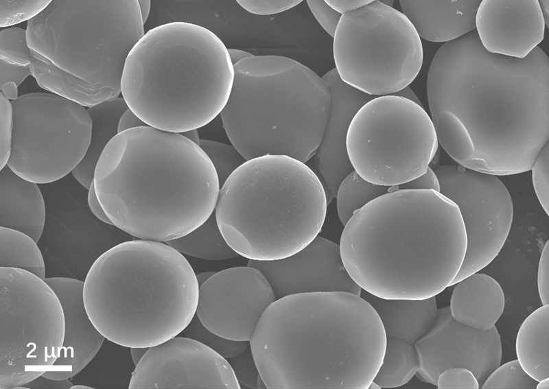
Aluminum nitride (AlN) ceramici s an advanced ceramic material serving as a key thermal management solution in the semiconductor and 5G industries. Its exceptional thermal conductivity (170-230 W/mK) and reliable electrical insulation properties heavily depend on one core characteristic: sintering activity. Simply put, sintering activity determines whether high-purity AlN powder can achieve high densification efficiently at elevated temperatures to form high-performance ceramics for electronic packaging, heat spreaders, and substrate applications.


What is Sintering Activity?

Sintering activity refers to the ability of a ceramic powder to form a dense structure during heat treatment. Powder with high activity enables low-temperature sintering, achieving high density in shorter timeframes, significantly reducing production costs while enhancing thermal performance and mechanical reliability.


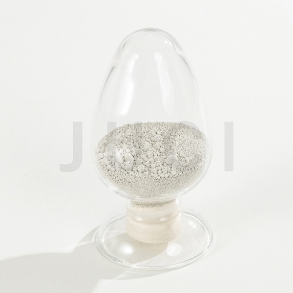
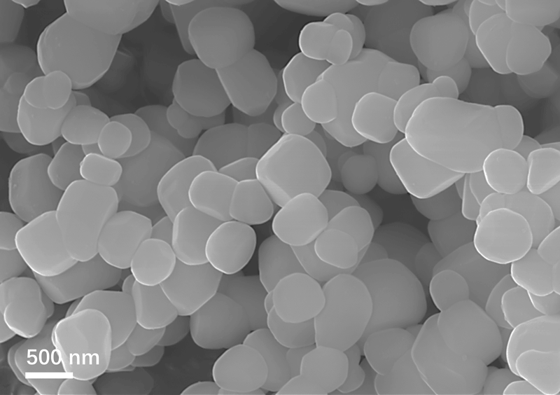
High sintering activity AlN powder


Three Key Factors Influencing Sintering Activity

1. Powder Particle Size

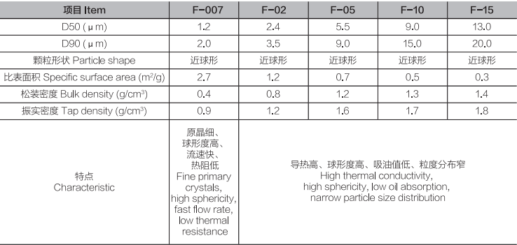
Fine powder with submicron particles provides larger specific surface area and higher surface energy, resulting in stronger sintering drive and improved microstructure development.

2. Oxygen Content Control

Excessive oxygen content leads to alumina formation, creating interfacial barriers that degrade thermal conductivity and hinder densification process. Maintaining low oxygen levels is critical for high thermal conductivity AlN.

3. Sintering Additives

Yttria (Y₂O₃) additives react with surface oxides to form liquid phase sintering, enhancing mass transport and pore elimination. This enables pressureless sintering of high-density AlN ceramics with optimized grain boundary engineering.


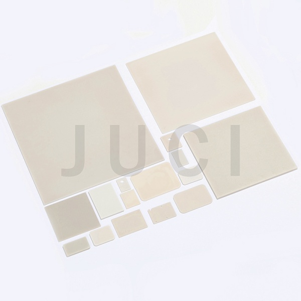
High density AlN ceramics


How to Optimize Sintering?

1、Use high-purity AlN powder with controlled particle size distribution

2、Implement atmospheric sintering under nitrogen environment

3、Apply sintering aids for microstructure control

4、Utilize non-oxide additives for thermal conductivity enhancement

5、Optimize sintering profile for cost-effective production


Conclusion

Sintering activity is a critical material property determining the end-performance of AlN ceramics in power electronics, LED packaging, and RF applications. Mastery of sintering technology enables manufacturers to produce high-thermal-conductivity substrates with superior mechanical strength and reliability performance, positioning AlN as the material of choice for next-generation thermal management solutions.


About Xiamen Juci Technology Co., LTD


Xiamen Juci Technology Co., Ltd. is a leading Chinese manufacturer of aluminum nitride (AlN) powder, utilizing the carbothermal reduction method for its production. The aluminum nitride powder produced through this process exhibits exceptionally high sintering activity and ultra-high purity. Such powder enables the fabrication of highly dense aluminum nitride ceramics, providing superior thermal management solutions for 5G communications, semiconductors, and other advanced industries.


Media Contact:
Xiamen Juci Technology Co., Ltd.

Phone: +86 592 7080230
Email: miki_huang@chinajuci.com

Website: www.jucialnglobal.com.

Control Valve The Precise "Commander" of Fluid Control

2025-09-09

In the grand stage of pipeline fluid control, the control valve is undoubtedly the "leading role". Today, let's get to know this "big shot" that can precisely regulate the fluid.


What is a control valve?

A control valve is a type of valve used to regulate parameters such as the flow rate, pressure, and temperature of the fluid in a pipeline. It is like an intelligent "traffic policeman". According to the needs of the system, it can flexibly adjust the valve opening, thereby controlling the flow state of the fluid. By receiving signals from various sensors, the control valve can react in real time to ensure that the fluid always operates according to the predetermined parameters, providing a strong guarantee for the stable operation of the entire system.


The Diverse Types of Control Valves

Pneumatic Control Valve: Using compressed air as the power source, it drives the valve to act by controlling the air pressure. It has a fast response speed and high control precision, just like an agile "athlete". It is often used in industrial automation production lines with high requirements for control precision and fast response speed. For example, in the feed control of the reactor in chemical production, it can accurately regulate the material flow rate to ensure the stability of the production process.

Electric Control Valve: Using an electric motor as the driving device, it controls the opening and closing of the valve through electrical signals. It is easy to operate and is convenient for realizing remote control, just like a "commander" that can be remotely controlled. In the building automation system, the electric control valve is often used for the temperature regulation of the air conditioning system. According to the changes in indoor and outdoor temperatures, it can automatically adjust the flow rate of chilled water or hot water to create a comfortable indoor environment for people.

Self-operated Control Valve: It does not require external energy and relies on the energy of the fluid itself to achieve regulation. It is like a self-sufficient "lone ranger" that can automatically adjust the valve opening according to parameters such as the pressure and temperature of the fluid in the pipeline. For example, in the heating system, the self-operated control valve can automatically adjust the flow rate of steam or hot water according to the needs of the user end to achieve energy-saving and efficient heating.


The Application Scenarios of Control Valves

Petrochemical Industry: In processes such as petroleum refining and chemical production, it is necessary to precisely control the flow rate and pressure of various fluids. The control valve can ensure that chemical reactions occur under appropriate conditions and prevent safety accidents caused by the out-of-control of fluid parameters. It is the "safety guardian" of chemical production.

Power Industry: In thermal power plants, the control valve is used to control the flow rate and pressure of steam, regulate the combustion efficiency of the boiler, and ensure the stable operation of the power generation equipment. It is like the "power regulator" of the power plant, contributing to the stable supply of electricity.

Environmental Protection and Water Treatment: In sewage treatment plants, the control valve can adjust the dosage of the chemical dosing device according to the changes in the flow rate and water quality of the sewage, and control the flow velocity of the sewage in each treatment process to ensure that the sewage treatment effect meets the standards. It is the "green facilitator" of environmental protection undertakings.

Plug Valve The Versatile Expert in Pipeline Fluid Control

2025-09-09

Plug Valve: The Versatile Expert in Pipeline Fluid Control


In the vast network of pipeline systems, the plug valve is indeed a capable expert in controlling fluids. Its core component is a rotatable plug, which is just like a flexible "rotary switch". There are through - holes of different shapes distributed on the plug. As the plug rotates, the through - holes align with or stagger from the pipeline, thus ingeniously realizing the on - off control and flow regulation of the fluid. This process is like equipping the pipeline with a magical "rotary key", which can easily control the flow direction and flow rate of the fluid.


The family of plug valves is rich and diverse in types. The ordinary plug valve is the most basic type, with a simple structure and relatively low cost. Its plug is usually cylindrical, and the rotation operation is very convenient. This kind of plug valve is suitable for occasions with low requirements for sealing performance and clean media, such as some simple water pipeline systems. In these scenarios, it is like a simple and unadorned "basic guard", silently safeguarding the normal flow of ordinary fluids. Although it seems ordinary, it is indispensable.


The oil - sealed plug valve is an upgraded version of the ordinary plug valve, with an additional oil - sealing device. This layer of oil seal is just like putting on a solid "sealing armor" for the plug, greatly improving the sealing performance of the valve. Therefore, it is often used in occasions where high - sealing - performance fluids such as oil and natural gas are transported. In these key transportation processes, the oil - sealed plug valve is like a meticulous and rigorous "sealing guard", always on high alert to ensure the safe and leak - free transportation of energy, providing a solid guarantee for the stable operation of industrial production and energy supply.


The plug - ball valve combines the advantages of both the plug valve and the ball valve, with a more ingenious plug design. It not only has good sealing performance to effectively prevent fluid leakage but also has the characteristic of fast opening and closing. In some industrial scenarios with extremely high requirements for fluid - cutting speed, such as emergency - cutting devices in chemical production, the plug - ball valve is like an agile and efficient "emergency vanguard". In critical moments, it can respond quickly and cut off the fluid rapidly to avoid potential dangers and losses, ensuring the safety and stability of the production process.


In terms of urban water supply and drainage systems, the plug valve plays an important role in water supply and drainage pipe networks. It can be opened and closed quickly, providing great convenience for pipeline maintenance and repair work, and effectively ensuring the stable operation of the urban water system. It can be called the "water - flow commander" in the field of water supply and drainage. Whether it is the daily water - supply scheduling or the emergency treatment in case of sudden situations, the plug valve can play a key role to ensure the unobstructed "lifeline" of the city.


In the petrochemical industry, the plug valve is widely used due to its good sealing performance and excellent corrosion resistance. In this challenging field, whether it is transporting highly corrosive chemical raw materials or handling flammable and explosive petroleum products, the plug valve can give full play to its own advantages. It is like a loyal and reliable "safety guardian", always sticking to its post to ensure the safety and stability of the production process, escorting the vigorous development of the petrochemical industry.


In the field of gas transportation, for gas, a flammable and explosive fluid, the sealing performance is undoubtedly crucial. The unique oil - seal design of the plug valve makes it perform excellently in gas - transportation pipelines, just like a trustworthy "gas guard", safeguarding the gas - using safety of every household. It not only ensures the stable supply of gas but also provides a reliable safety guarantee for people's daily lives, allowing people to use gas resources with peace of mind.


Although the plug valve may not be eye - catching in appearance, with its unique structure and diverse performance, it plays an irreplaceable and important role in the field of pipeline fluid control. It is like a silent "rotary - core hero", providing all - round escort for our production and life in its own unique way, leaving a solid and reliable mark in all aspects of industrial production and daily life.

Factors Influencing Shrinkage in Polymer Materials

2025-09-04

In the field of polymer applications, shrinkage rate is a critical parameter that profoundly affects the dimensional accuracy, performance, and final application outcomes of polymer products.


Whether in everyday plastic items or precision components used in advanced industrial sectors, understanding and controlling the shrinkage of polymer materials is essential to ensuring product quality and functionality.


In this article, we will delve into the key factors influencing polymer shrinkage and explore effective methods to reduce shrinkage.


1. Definition of Shrinkage Rate in Polymer Materials
The shrinkage rate of polymer materials refers to the percentage difference between the dimensions of a plastic part at the molding temperature and its dimensions after being removed from the mold and cooled to room temperature. It directly reflects the degree of dimensional reduction of the plastic part after cooling outside the mold.

To illustrate simply, it’s like placing a plastic model at a high temperature into a mold for forming; once cooled, its size will be smaller than its size at the molding temperature inside the mold. This reduction ratio is the shrinkage rate.

The shrinkage rate is calculated by the formula:


where R before is the dimension at the molding temperature, and R after is the dimension after cooling to room temperature.


Due to differences in molecular structure, chemical composition, and other factors, various polymer materials have different shrinkage rates. This makes considering shrinkage rate especially important during material selection and molding process design.


2. Factors Affecting Shrinkage Rate of Polymer Materials
Influence of Raw Materials

1. Different Types of Raw Materials

The shrinkage rates vary significantly among different types of polymer materials.

For example, long fiber-reinforced modified materials typically have a shrinkage rate of approximately 1.2% to 1.5%.


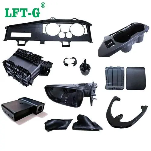
PP homopolymer 40% Long Glass Fiber Reinforced


2. Crystallinity of Raw Materials
When a material has a high degree of crystallinity, its molecular chains are tightly and orderly arranged. During cooling, the chains change from a disordered molten state to an ordered crystalline state, causing significant shrinkage. The tightly packed chains in the crystalline regions reduce the material’s volume, resulting in a higher shrinkage rate. In contrast, amorphous (non-crystalline) materials generally have lower shrinkage.

A simple analogy is stacking wood: randomly piled wood takes up more space, while neatly stacked wood occupies less volume.


3. Molecular Weight of Raw Materials
When the molecular weight is high, the intermolecular forces between chains are stronger, making chain movement more difficult. During molding and cooling, the chains cannot easily rearrange and pack tightly, resulting in a lower shrinkage rate. In contrast, materials with lower molecular weight have more mobile chains that can rearrange and aggregate more easily during cooling, leading to a higher shrinkage rate.


Influence of Molding Process
1. Molding Temperature
Raising the molding temperature increases molecular chain mobility and improves melt flow, allowing more molten material to fill the mold cavity. However, higher temperatures also increase the driving force for shrinkage during cooling. On the other hand, the longer gate-sealing time at higher temperatures allows more melt to enter the cavity, increasing molding density. Overall, the combined effect often leads to a reduced shrinkage rate.

2. Holding Pressure
Higher holding pressure during molding compresses more melt into the cavity, compensating for the volume reduction caused by cooling shrinkage and thereby reducing the shrinkage rate. For crystalline materials, the effect of holding pressure on shrinkage shows a curved downward trend, while for some amorphous materials, the shrinkage rate decreases linearly with increasing holding pressure.

3. Melt Temperature
A higher melt temperature increases molecular thermal motion and improves flowability, making it easier to completely fill the mold cavity. For crystalline materials, it can also influence crystallization behavior, thereby affecting shrinkage. Generally, increasing melt temperature reduces shrinkage, but excessive temperature may lead to material degradation.

4. Mold Temperature
Lower mold temperatures cause the melt to solidify more quickly, shortening cooling time and reducing shrinkage reactions, thus lowering shrinkage rates. Higher mold temperatures slow cooling, allowing more shrinkage to occur.

5. Holding Time
A longer holding time allows the melt to continue filling gaps caused by cooling shrinkage under pressure, reducing the shrinkage rate. However, excessive holding time can increase the molding cycle and may cause stress concentration in the product.

6. In-Mold Cooling Time
For large plastic products with thick walls, sufficient in-mold cooling time is necessary to ensure full cooling and solidification. This helps molecular chains stabilize in their final arrangement, resulting in stable or even reduced shrinkage. Insufficient cooling time may cause continued shrinkage after demolding, leading to dimensional deviations.

7. Injection Speed
For thin-walled products, a higher injection speed allows the melt to quickly fill the cavity, but can introduce higher shear stress, causing molecular chain orientation and anisotropic shrinkage. A slower injection speed may result in uneven filling, which also affects shrinkage.


Influence of Structure
1. Wall Thickness of Plastic Products
An increase in wall thickness slows the internal cooling rate, allowing more complete crystallization and a higher degree of crystallinity, which leads to increased shrinkage. For some amorphous materials, the effect of wall thickness on shrinkage shows no clear pattern.

2. Presence of Inserts in Injection-Molded Parts
When injection-molded parts contain metal inserts, the difference in thermal expansion coefficients between the metal and the polymer can cause uneven shrinkage during cooling, generating internal stress. This may result in non-uniform shrinkage around the inserts, potentially causing warpage, cracking, or other defects.

3. Shape of the Injection-Molded Part
Complex shapes—such as parts with transitions between thin and thick walls, ribs, bosses, or other features—can lead to uneven shrinkage. Thin sections cool quickly and shrink less, while thick sections cool slowly and shrink more, creating shrinkage differences within the same part. Asymmetrical parts are also more prone to non-uniform shrinkage.

4. Shrinkage in the Length vs. Thickness Direction
In injection molding, the molecular chains in the melt tend to be more oriented in the flow direction (length direction), resulting in relatively lower shrinkage. Perpendicular to the flow (thickness direction), the molecular chains are less oriented, leading to relatively higher shrinkage.


Influence of Mold Structure
1. Gate Size
In injection molding, a larger gate reduces melt flow resistance, allows more material to enter the cavity, ensures more uniform pressure distribution, and increases molding density, resulting in a lower shrinkage rate. Conversely, a smaller gate increases shrinkage.

2. Shrinkage in Directions Parallel and Perpendicular to the Gate
In the flow (parallel) direction, molecular chains are more oriented, leading to smaller shrinkage during cooling. In the direction perpendicular to the gate, molecular chain orientation is lower, resulting in greater shrinkage and potentially causing warpage or deformation.

3. Shrinkage Differences Between Areas Near and Far from the Gate
In large molds, areas far from the gate experience lower melt pressure, later filling, and weaker holding effects, resulting in relatively higher shrinkage. Areas near the gate generally have lower shrinkage.


Modification Methods to Reduce Shrinkage of Polymer Materials
Fiber Reinforcement
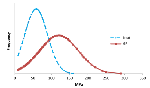
Taking polylactic acid (PLA) as an example, adding short glass fibers can significantly reduce its molding shrinkage. When the glass fiber content reaches a certain proportion, the shrinkage of PLA composites decreases noticeably. Compared with short glass fibers, long glass fiber-reinforced polymers exhibit even lower shrinkage, with consistent shrinkage in both longitudinal and transverse directions. Whisker-reinforced polymers also show low shrinkage; for instance, PLA reinforced with calcium sulfate whiskers has lower shrinkage than PLA reinforced with glass fibers.

Long Fiber Reinforced Polymers


Inorganic Filler Reinforcement
Filler Shape: In polyhydroxyalkanoates (PHA), platelet fillers (e.g., talc) are more effective in reducing shrinkage than needle-like, granular, or spherical fillers. Platelet fillers form oriented structures inside the material, restricting molecular chain movement and shrinkage.

Filler Particle Size: For the same filler in polybutylene succinate (PBS), smaller particles lead to a greater reduction in shrinkage. Finer fillers disperse more uniformly and interact more strongly with molecular chains, enhancing shrinkage inhibition.

Filler Surface Treatment: Treating calcium carbonate with a coupling agent before blending with PLA improves compatibility, strengthens filler-matrix interaction, and more effectively reduces shrinkage.

Filler Content: In PHA, adding more calcium carbonate gradually decreases shrinkage. However, excessive filler may affect other material properties, so an optimal balance is necessary.

Reducing Crystallinity
Adding Nucleating Agents: Certain nucleating agents in PLA refine crystal grains and lower overall crystallinity, reducing shrinkage. They generate numerous crystallization nuclei in the melt, preventing the formation of large spherulites that cause shrinkage.

Blending with Other Resins: In PBS, blending a small amount of other biobased resins, such as PLA, disrupts crystallization and reduces shrinkage. While the shrinkage reduction effect is smaller than that of fiber or inorganic filler reinforcement, resin blending can improve overall performance.

Blending with Elastomers
PLA can be blended with elastomers such as POE, EPDM, or SBS. When the elastomer content is below 5%, the effect on PLA shrinkage is similar for all types. Above 5%, the effect follows the order: POE > EPDM > SBS, consistent with their toughening efficiency. Combining inorganic fillers with elastomers in PLA further improves shrinkage reduction.

Chemical Crosslinking and Grafting
For PLA, grafting introduces other functional groups or chain segments into the molecular chain, disrupting chain regularity, reducing crystallinity, and thus lowering shrinkage. For polyhydroxyalkanoates (PHA), crosslinking significantly decreases the linear thermal expansion coefficient. Crosslinking restricts chain mobility, so during heating or cooling, chain extension and contraction are limited, resulting in reduced shrinkage.


Polymer shrinkage is a critical parameter influenced by multiple factors. From raw material selection to molding process control, and from product structure to mold design, every stage affects shrinkage. Understanding these factors and mastering modification methods to reduce shrinkage is essential for improving the quality, dimensional accuracy, and performance stability of polymer products.


Carbon Fiber Composite Applications for Automotive Lightweighting

2025-09-04

With global climate warming and the increasing depletion of fossil fuel resources, promoting green energy and sustainable development has become a global consensus. As a product of modern industrial civilization, the automotive industry is facing unprecedented pressure to save energy and reduce emissions, making vehicle lightweighting an important approach to address these challenges. Among various lightweight materials, carbon fiber composites stand out for their exceptional specific strength, specific modulus, and design flexibility, and are being widely applied in the automotive industry.


Applications of Carbon Fiber Composites in Automobiles


1. Vehicle Body Structural Components
First, in terms of exterior panels, carbon fiber composites are widely used in parts such as doors and engine hoods. These components not only require excellent mechanical performance but also need to meet multiple functional requirements, including aerodynamics and noise-vibration characteristics. By designing optimal carbon fiber layup schemes and selecting high-performance resin matrices, the weight of components can be reduced while significantly enhancing their stiffness, strength, and impact resistance, also allowing for more streamlined design aesthetics.

In the field of body frame structural components, due to their outstanding specific strength and specific modulus, carbon fiber composites can replace traditional metal materials. Through advanced molding and joining processes, it is possible to achieve integrated manufacturing of the body frame, greatly reducing the number of joints and improving both structural integration and lightweight performance. For example, one automobile adopts a full carbon fiber composite passenger cabin, and through modular design and process optimization, achieves up to a 62% reduction in weight while improving crash safety performance by more than 30%.


2. Chassis Systems
In suspension systems, carbon fiber composites are an excellent material choice for key components such as springs, shock absorbers, and control arms. Take shock absorbers as an example: those made from carbon fiber composites are not only lighter in weight but also exhibit 2–3 times higher fatigue resistance, resulting in more responsive and comfortable suspension dynamics. Using carbon fiber composite shock absorbers can reduce the weight of the suspension system by 15%–25% while decreasing bumps and vibrations by 10%–15%, effectively improving ride comfort.


In the field of drive shafts, carbon fiber composites can achieve a 25%–40% weight reduction while maintaining strength and stiffness, and reduce vibration and noise levels by 3–8 dB, significantly enhancing transmission efficiency as well as NVH (noise, vibration, and harshness) performance.


3. Powertrain Systems
Engine covers made from carbon fiber composites are first molded by laying prepreg or dry fibers into a mold, followed by high-temperature, high-pressure curing to form a lightweight cover that closely matches the engine bay contours. Compared with traditional materials such as aluminum alloys, carbon fiber composite engine covers can achieve a 30%–40% reduction in weight and increase cover stiffness by 20%–30%, effectively reducing vibration and noise while improving the NVH (noise, vibration, and harshness) performance of the engine compartment.


Key Technologies for the Application of Carbon Fiber Composites

1. Selection of Fibers and Matrices
For carbon fiber selection, high-strength fibers such as T700 and T800 are commonly used due to their high specific strength and specific modulus. For matrix selection, high-performance resins such as epoxy and polyimide are widely applied because of their excellent mechanical properties, thermal resistance, and processability. Statistics show that using T800 carbon fiber with an epoxy resin matrix can achieve a tensile strength of over 2500 MPa and a specific modulus exceeding 150 GPa.

2. Molding Processes

In automotive lightweighting, the choice and optimization of molding processes are key to achieving efficient manufacturing and high-performance components. Common processes include compression molding, filament winding, and pultrusion. Compression molding uses molds and pressure to combine prepregs or dry fibers with a resin matrix, producing composite components with complex shapes and excellent properties. This process is suitable for large-scale production, achieving high efficiency and dimensional accuracy. Using compression molding can increase production efficiency of composite components by 20%–30% and control dimensional tolerances within ±0.2 mm.


Filament winding involves impregnating continuous fiber bundles with resin and winding them along predetermined paths onto a mandrel. After curing, hollow composite components are obtained. This process allows precise control of fiber orientation, enabling the fabrication of high-strength, high-stiffness tubular and cylindrical parts. Additionally, filament winding significantly improves material utilization and reduces waste, increasing material efficiency by 30%–40%.


Pultrusion combines pulling and extrusion to pass resin-impregnated continuous fiber bundles through a forming die, producing profiles and sheets with stable cross-sectional shapes. This process offers high production efficiency, enables continuous manufacturing of profiles, and results in components with excellent mechanical properties and high dimensional accuracy.

3. Joining Techniques
Mechanical joining uses fasteners such as bolts and rivets to securely connect composite components to other structural parts. This method is simple, detachable, and suitable for reliable connections between different materials. Mechanical joining can effectively reduce stress concentration in the joint area, improving joint strength and fatigue life. With optimized bolt designs, the fatigue life of composite joints can be increased by 1.5–2 times. However, mechanical joining may introduce stress concentrations that weaken overall composite performance, so careful design and optimization are necessary.


Composite Joining Methods Types and Key Considerations

2025-09-04

Overview
Composite joining technology is a critical yet relatively weak link in the design and manufacturing of composite structures. Due to the anisotropy, brittleness, and low interlaminar strength of composites, their joining design differs significantly from metallic structures and requires special attention. The main joining methods can be categorized into three groups:


1. Mechanical Joining
Principle: Uses mechanical fasteners (bolts, screws, rivets, etc.) to connect composite-to-composite or composite-to-metal components, usually requiring drilled holes.

Advantages:
- High reliability and inspectability: joint condition is visible, enabling easier inspection and maintenance.

- Load transfer capability: suitable for primary load-bearing structures or highly loaded regions.

- Lower surface preparation requirements compared to adhesive bonding.

- Less sensitive to environmental factors such as humidity and temperature.

Disadvantages:
- Stress concentration: drilling breaks fiber continuity and causes stress concentration at hole edges, a primary cause of failure.

- Added weight: fasteners and reinforcements (washers, bushings) increase structural weight.

- Damage risk: drilling may induce delamination, fiber pull-out, or matrix micro-cracks.

- Galvanic corrosion: when using metal fasteners with carbon fiber composites, requiring titanium or stainless steel plus insulation.

- Fatigue life reduction due to hole-edge stress concentration.

Key Technical Points:
- Fastener selection: material (titanium alloy, stainless steel, composite fasteners), type (Hi-Lok bolts, blind rivets, Hi-Lite rivets), head shape (countersunk vs protruding).

- Hole preparation: precision low-damage drilling (diamond-coated drills, backing plates, optimized parameters), water-jet laser drilling.

- Fit: clearance fit preferred; interference fit may cause delamination.

- Torque control: accurate preload control to prevent loosening or crushing composites.

- Design rules: strict edge distance, pitch, and spacing guidelines.

2. Adhesive Bonding

Principle: Uses adhesives to bond composite parts together.

Advantages:

- No stress concentration: fiber continuity maintained, load distribution uniform.

- Lightweight: no fasteners or holes, reducing overall weight.

- Excellent fatigue performance due to uniform stress distribution.

- Sealing and damping properties: adhesive layer provides both.

- Suitable for thin-walled and complex geometries.

- Smooth, aesthetic surfaces.


Disadvantages:
- High surface preparation requirements: critical to remove release agents, contaminants; surface treatments (sanding, grit blasting, solvent cleaning, primer, plasma) are mandatory.
- Strength variability: highly dependent on process quality (surface prep, mixing, curing).
- Difficult inspectability and disassembly: cured joints are challenging to assess and remove nondestructively.
- Environmental sensitivity: adhesive properties degrade in hot/wet conditions.
- Weak in peel and cleavage loads compared to shear loads.
- Strict curing requirements (temperature, pressure, time).

Key Technical Points:
- Adhesive selection: based on service temperature, load type (shear, peel, tension), toughness, curing conditions (epoxy, acrylic, polyurethane, cyanoacrylate). Film adhesives vs paste adhesives depending on application.

- Surface preparation: cornerstone of bonding reliability, requiring standardized processes.

- Joint design: optimize for shear loads (single-lap, double-lap, scarf, stepped joints), minimize peel stresses, control adhesive thickness.

- Curing process control: precise temperature, pressure, heating rate, and dwell time.

- Nondestructive inspection: ultrasonic, radiography, thermography.

3. Hybrid Joining

Principle: Combines adhesive bonding and mechanical fastening in the same joint region.

Advantages:
- Higher efficiency and reliability: adhesive provides uniform load distribution, fasteners add fail-safe capability.

- Improved fatigue performance: fasteners arrest crack growth.

- Higher damage tolerance: multiple load paths.

- Reduced fastener hole precision requirements due to adhesive filling.

Disadvantages:
- Heavier and more complex than adhesive-only joints.

- Higher cost and process complexity.

- Potential interactions: tightening fasteners may disturb uncured adhesive, adhesive shrinkage may affect preload.

Applications: Critical joints requiring the highest safety and reliability, such as aircraft wing-to-fuselage connections.

Key Considerations in Composite Joint Design

- Load conditions: tension, compression, shear, peel, fatigue, impact.

- Material properties: ply orientation, stacking sequence, thickness, type of joined materials (composite-composite, composite-metal).

- Environmental factors: temperature, humidity, chemicals, UV exposure.

- Manufacturability: feasibility, cost, production cycle.

- Inspectability & maintainability: ability to inspect nondestructively and ease of repair/disassembly.

- Weight: minimizing weight is a core goal of composites.

- Cost: materials, manufacturing, maintenance.

- Failure modes: joints should be designed for predictable, non-catastrophic failure modes (e.g., bolt bearing failure, cohesive adhesive failure) while avoiding brittle fracture (e.g., net-tension, delamination, interfacial adhesive failure).
Trends in Composite Joining Technologies

- Advanced adhesives: improved temperature resistance, toughness, and durability; better surface treatment methods (e.g., plasma); more reliable NDT techniques (guided waves, nonlinear ultrasonics).

- Advanced mechanical joining: low-damage drilling, composite fasteners, smart fasteners with sensing capabilities.

- Hybrid joint optimization: deeper study of adhesive–bolt interactions and refined design tools.

- Integral/co-cured structures: reducing the need for joints via design and manufacturing innovations (e.g., 3D weaving, stitching, Z-pinning).

- Numerical simulation: high-fidelity finite element models capturing damage, contact, and adhesive behavior.

- Smart joints / SHM: embedded sensors in joint regions for real-time monitoring.

Conclusion

There is no universal joining method for composites; the choice depends on application requirements, load conditions, environment, cost, manufacturability, and maintenance needs.

- Adhesive bonding offers advantages in weight reduction, stress distribution, and fatigue but requires strict process control.

- Mechanical fastening excels in reliability, inspectability, and load transfer but adds stress concentration and weight.

- Hybrid joints combine the benefits of both, used in critical applications where safety margins are paramount.

Understanding each method’s principles, strengths, weaknesses, and technical requirements is fundamental to the successful design and application of composite structures.


Tags
#tt